The reactor is the heart of a chemical process. It is the only place in the process where
raw materials are converted into products, and reactor design is a vital step in the overall design of the process. Numerous texts have been published on reactor design, and a selection is given in the bibliography at the end of this chapter. The volumes by Rase (1977), (1990) cover the practical aspects of reactor design and include case studies of industrial reactors. The design of electrochemical reactors is covered by Pickett (1979), Rousar et al (1985) and Scott (1991). The treatment of reactor design in this section will be restricted to a discussion of the selection of the appropriate reactor type for a particular process, and an outline of the steps to be followed in the design of a reactor (Coulson., 1999).
The design of an industrial chemical reactor must satisfy the following requirements:
1. The chemical factors: the kinetics of the reaction. The design must provide sufficient residence time for the desired reaction to proceed to the required degree of conversion.
2. The mass transfer factors: with heterogeneous reactions the reaction rate may be controlled by the rates of diffusion of the reacting species; rather than the chemical kinetics.
3. The heat transfer factors: the removal, or addition, of the heat of reaction.
4. The safety factors: the confinement of hazardous reactants and products, and the control of the reaction and the process conditions.
The need to satisfy these interrelated, and often contradictory factors, makes reactor design a complex and difficult task. However, in many instances one of the factors will predominate and will determine the choice of reactor type and the design method.
1. Principal types of reactor
The following characteristics are normally used to classify reactor designs:
1. Mode of operation: batch or continuous.
2. Phases present: homogeneous or heterogeneous.
3. Reactor geometry: flow pattern and manner of contacting the phases
(i) stirred tank reactor;
(ii) tubular reactor;
(iii) packed bed, fixed and moving;
(iv) fluidised bed.
1.1. Batch or continuous processing
In a batch process all the reagents are added at the commencement; the reaction proceeds, the compositions changing with time, and the reaction is stopped and the product withdrawn when the required conversion has been reached. Batch processes are suitable for small-scale production and for processes where a range of different products, or grades, is to be produced in the same equipment; for instance, pigments, dyestuffs and polymers.

In continuous processes the reactants are fed to the reactor and the products withdrawn continuously; the reactor operates under steady-state conditions. Continuous production will normally give lower production costs than batch production, but lacks the flexibility of batch production. Continuous reactors will usually be selected for large-scale production. Processes that do not fit the definition of batch or continuous are often referred to as semi-continuous or semi-batch. In a semi-batch reactor some of the reactants may be added, or some of the products withdrawn, as the reaction proceeds. A semi-continuous process can be one which is interrupted periodically for some purpose; for instance, for the regeneration of catalyst.
1.2. Homogeneous and heterogeneous reactions
Homogeneous reactions are those in which the reactants, products, and any catalyst used
form one continuous phase: gaseous or liquid.
Homogeneous gas phase reactors will always be operated continuously; whereas liquid phase reactors may be batch or continuous. Tubular (pipe-line) reactors are normally used for homogeneous gas-phase reactions; for example, in the thermal cracking of petroleum crude oil fractions to ethylene, and the thermal decomposition of dichloroethane to vinyl chloride. Both tubular and stirred tank reactors are used for homogeneous liquid-phase reactions.
In a heterogeneous reaction two or more phases exist, and the overriding problem in the reactor design is to promote mass transfer between the phases. The possible combination of phases are:
1. Liquid-liquid: immiscible liquid phases; reactions such as the nitration of toluene or benzene with mixed acids, and emulsion polymerisations.
2. Liquid-solid: with one, or more, liquid phases in contact with a solid. The solid may be a reactant or catalyst.
3. Liquid-solid-gas: where the solid is normally a catalyst; such as in the hydrogenation of amines, using a slurry of platinum on activated carbon as a catalyst.
4. Gas-solid: where the solid may take part in the reaction or act as a catalyst. The reduction of iron ores in blast furnaces and the combustion of solid fuels are examples where the solid is a reactant.
5. Gas-liquid: where the liquid may take part in the reaction or act as a catalyst.
1.3. Reactor geometry (type)
The reactors used for established processes are usually complex designs which have been developed (have evolved) over a period of years to suit the requirements of the process, and are unique designs. However, it is convenient to classify reactor designs into the following broad categories.
1.3.1. Stirred tank reactors
Stirred tank (agitated) reactors consist of a tank fitted' with a mechanical agitator and a cooling jacket or coils. They are operated as batch reactors or continuously. Several reactors may be used in series.
The stirred tank reactor can be considered the basic chemical reactor; modelling on a large scale the conventional laboratory flask. Tank sizes range from a few litres to several thousand litres. They are used for homogeneous and heterogeneous liquid-liquid and liquid-gas reactions; and for reactions that involve finely suspended solids, which are held in suspension by the agitation. As the degree of agitation is under the designer's control, stirred tank reactors are particularly suitable for reactions where good mass transfer or heat transfer is required.
When operated as a continuous process the composition in the reactor is constant and the same as the product stream, and, except for very rapid reactions, this will limit the conversion that can be obtained in one stage.
The power requirements for agitation will depend on the degree of agitation required and will range from about 0.2 kW/m3 for moderate mixing to 2 kW/m3 for intense mixing.
1.3.2. Tubular reactors
Tubular reactors are generally used for gaseous reactions, but are also suitable for some liquid-phase reactions.
If high heat-transfer rates are required, small-diameter tubes are used to increase the surface area to volume ratio. Several tubes may be arranged in parallel, connected to a manifold or fitted into a tube sheet in a similar arrangement to a shell and tube heat exchanger. For high-temperature reactions the tubes may be arranged in a furnace.
The pressure-drop and heat-transfer coefficients in empty tube reactors can be calculated using the methods for flow in pipes.
1.3.3. Packed bed reactor
There are two basic types of packed-bed reactor: those in which the solid is a reactant, and those in which the solid is a catalyst. Many examples of the first type can be found in the extractive metallurgical industries.

1.3.4.Fluidised bed reactor
The essential features of a fluidised bed reactor is that the solids are held in suspension by the upward flow of the reacting fluid; this promotes high mass and heat-transfer rates and good mixing. Heat-transfer coefficients in the order of 200 W/m2°C to jackets and internal coils are typically obtained. The solids may be a catalyst; a reactant in fluidized combustion processes; or an inert powder, added to promote heat transfer.
Though the principal advantage of a fluidised bed over a fixed bed is the higher heat transfer rate, fluidised beds are also useful where it is necessary to transport large quantities of solids as part of the reaction processes, such as where catalysts are transferred to another vessel for regeneration.
Fluidisation can only be used with relatively small sized particles, <300 μm with gases. A great deal of research and development work has been done on fluidised bed reactors in recent years, but the design and scale up of large diameter reactors is still an uncertain process and design methods are largely empirical.
The principles of fluidisation processes are covered in Volume 2, Chapter 6. The design
of fluidised bed reactors is discussed by Rase (1977).
2. Design procedure
A general procedure for reactor design is outlined below:
1. Collect together all the kinetic and theraiodynamic data on the desired reactionand the side reactions. It is unlikely that much useful information will be gleaned from a literature search, as little is published in the open literature on commercially attractive processes. The kinetic data required for reactor design will normally be obtained from laboratory and pilot plant studies. Values will be needed for the rate of reaction over a range of operating conditions: pressure, temperature, flow-rate and catalyst concentration. The design of experimental reactors and scale-up is discussedby Rase (1977) and Jordan (1968).
2. Collect the physical property data required for the design; either from the literature, by estimation or, if necessary, by laboratory measurements.
3. Identify the predominant rate-controlling mechanism: Mnetic, mass or heat transfer. Choose a suitable reactor type, based on experience with similar reactions, or from the laboratory and pilot plant work.
4. Make an initial selection of the reactor conditions to give the desired conversion and yield.
5. Size the reactor and estimate its performance. Exact analytical solutions of the design relationships are rarely possible; semiempirical methods based on the analysis of idealised reactors will normally have to be used.
6. Select suitable materials of construction.
7. Make a preliminary mechanical design for the reactor: the vessel design, heat-transfer surfaces, internals and general arrangement.
8. Cost the proposed design, capital and operating, and repeat steps 4 to 8, as necessary, to optimise the design.
In choosing the reactor conditions, particularly the conversion, and optimising the design, the interaction of the reactor design with the other process operations mast not be overlooked. The degree of conversion of raw materials in the reactor will determine the size, and cost, of any equipment needed to separate and recycle unreacted materials. In these circumstances the reactor and associated equipment must be optimised as a unit.
Design of the reactor is no routine matter, and many alternatives can be proposed for a process. In searching for the optimum it is not just the cost of the reactor that must be minimized. One design may have low reactor cost, but the materials leaving the unit may be such that their treatment requires a much higher cost than alternative designs. Hence, the economics of the overall process must be considered.
Reactor design uses information, knowledge, and experience from a variety of areas-thermodynamics, chemical kinetics, fluid mechanics, heat transfer, mass transfer, and economics. Chemical reaction engineering is the synthesis of all these factors with the aim of properly designing a chemical reactor.
To find what a reactor is able to do we need to know the kinetics, the contacting pattern and the performance equation. This is shown schematically in the figure below :


Figure 1.1 Typical chemical process.
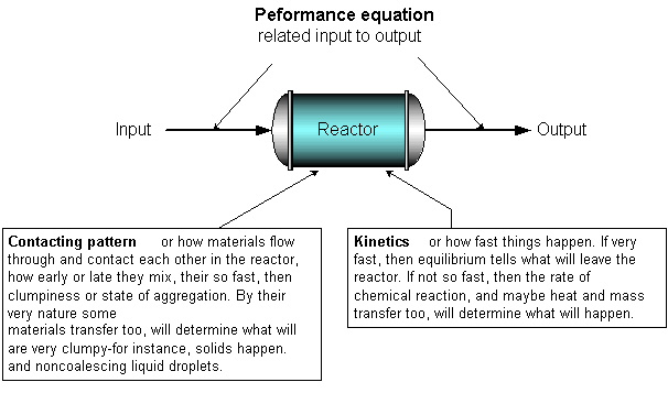
Figure 1.2 Information needed to predict what a reactor can do.
Much of this book deals with finding the expression to relate input to output for various kinetics and various contacting patterns, or
output = f [input, kinetics, contacting]
This is called the performance equation. Why is this important? Because with this expression we can compare different designs and conditions, find which is best, and then scale up to larger units. (Levenspiel, 1999)
4. REFERENCES
Coulson & Richardson's,1999, CHEMICAL ENGINEERING, vol. 2, Chemical Engineering Design, Butterworths
Levenspiel, O., 1999, Chemical Reaction Engineering, 3rd ed., John Wiley & Sons
Rase, H. F., 1977, Chemical Reactor Design for Process Plants, 2 volumes, John Wiley & Sons
Rase, H. F., 1990, Fixed~bed Reactor Design and Diagnostics, Butterworths
Perry, R. H., Green, D. W. and Maloney, J.O., 1997, Perry's Chemical Engineers' Handbook, 7th ed, McGraw-Hill.
Pickett, D. J., 1977, Electrochemical Reactor Design , Elsevier .
Rousar, I, Mich A, K. and Kimla, A., 1985, Electrochemical Engineering, 2 vols., Butterworths.
Walas, S, M., 1990, Chemical Process Equipment: Selection and Design , Butterworths.
Tidak ada komentar:
Posting Komentar